The SO-101 Robot Arms
For this module, you will be implementing the inverse kinematics algorithm from Lab 7 on hardware. The goal is to pick up two separate blocks and stack them on top of eachother.
Before completing this week’s lab, make sure that your inverse kinematics are working in simulation. If you are having difficulty, try revisiting the instructions for Lab 7 which have since been updated.
Outline
- Assignment Part 0: Test Inverse Kinematics Accuracy on Hardware
- Assignment Part 1: Pick and Place for One Block
- Assignment Part 2: Pick and Place to Stack Two Blocks
- Assignment Part 3 (Optional): Pick and Place to Stack Three Blocks
- Suggested Improvements
- Submission Details
Assignment Part 0: Test Inverse Kinematics Accuracy on Hardware
Before starting the pick-and-place task, you should first verify that your inverse kinematics implementation is accurate on hardware. To do this, you can write a simple script that moves the robot to a known position, and compare it to the actual position using the acrylic grid. Below is an example script that moves the robot to a specified position using your inverse kinematics function.
import time
from so101_utils import load_calibration, move_to_pose, hold_position, setup_motors
from so101_inverse_kinematics import get_inverse_kinematics

# CONFIGURATION VARIABLES
PORT_ID = "/dev/tty.usbmodem5A460848371" # REPLACE WITH YOUR PORT!
ROBOT_NAME = "follower-1"

# Set
'''
This is the format of the goal position dictionary used for goal position sync write.
The gripper command takes values of 0-100, while the other joints take values of degrees, based on
the settings specified in the bus initialization.
'''
desired_ee = [0.2, 0.0, 0]  # x, y, z in meters
desired_configuration = get_inverse_kinematics(desired_ee)
move_time = 2.0  # seconds to reach desired position
hold_time = 10.0  # total time to hold at

# ------------------------
# Configure motors and load calibration:
calibration = load_calibration(ROBOT_NAME)
bus = setup_motors(calibration, PORT_ID)

# Record starting position
starting_pose = bus.sync_read("Present_Position")
print("Starting Pose:", starting_pose)

# Move to desired
move_to_pose(bus, desired_configuration, move_time)

# Hold position for "hold_time" seconds
hold_position(bus, hold_time)

# Move back to starting position
move_to_pose(bus, starting_pose, move_time)

# Before terminating the program, disable torque on the motors
bus.disable_torque()
You will know if the end-effector position is accurate if the gripper is centered over the specified end-effector position on the grid. Try a few different end-effector positions to determine if you’re constantly consist, sometimes consistent, or constantly off. If you have any issues, try the following troubleshooting steps:
Adjust Acrylic Grid “Zero”
I’ve confirmed that our grids are accurate, but we can still correct for constant offsets (the same offset is observed for several different desired positions) by modifying the desired target position within the get_inverse_kinematics function call (in so101_inverse_kinematics.py). This can also be used to account for the increased z-height due to the metal mounts for the lab so101 robot arms. To do this, simply adjust the target_position variable before calculating the inverse kinematics, as shown below. I recommend the following offset to account for the metal base (if you have not already accounted for the mount height in your z-coordinate):
def get_inverse_kinematics(target_position, target_orientation):
    "Geometric appraoch specific to the so-101 arms"

    # Adjust the target position to account for metal platform height
    target_position[2] -= 0.015

    ...
Check Calibration
To check if your calibration is correct, you can command the robot arm to the “home” position (all joint angles set to zero) and see if the end-effector is in the expected location. If it is not, you may need to redo your calibration. When redoing your calibration, make sure to move each joint slowly and without over extending (or underextending!) the joint limits. The calibration process assumes the “zero” position as the middle of the joint limits achieved during calibration. So if you over extend a joint during calibration, the zero position will be offset. You can implement a calibration test by replacing the desired_configuraiton variable in the above code with the following:
desired_position = {
    'shoulder_pan': 0.0,   # degrees
    'shoulder_lift': 0.0,
    'elbow_flex': 0.0,
    'wrist_flex': 0.0,
    'wrist_roll': 0.0,
    'gripper': 0.0           # 0-100 range
}
As a reminder, the home position should look like this: 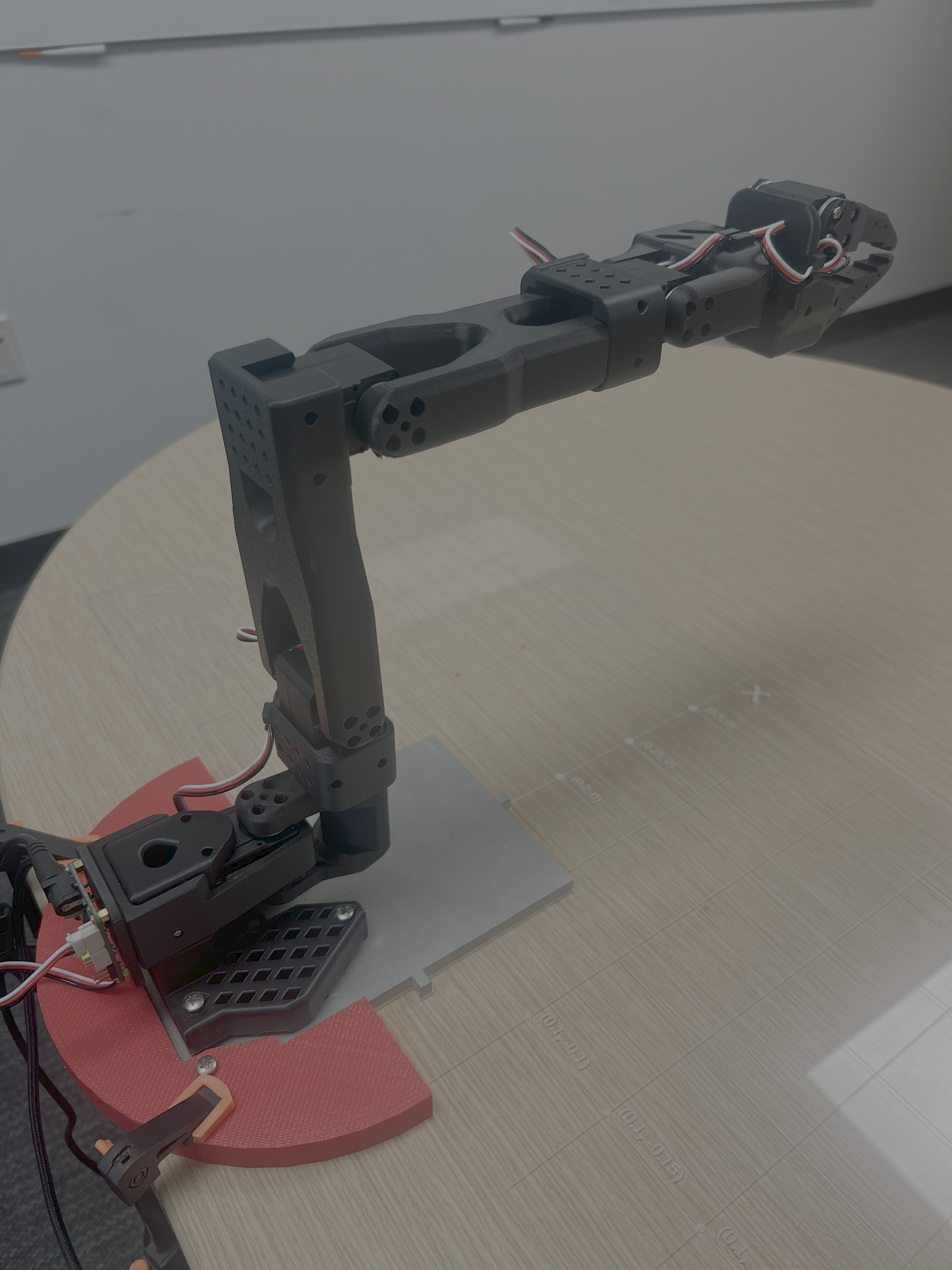
If any of the joints have a small offset even after recalibration, you can manually add an offset to the joint in the move_to_pose function within so101_utils.py. To do this, I recommend making a helper function called offset_config. For example, my manipulator arm needed to add 2 degrees to the shoulder_lift and subtract 4 degrees from the elbow_flex. Here is an example implementation of the offset_config function:
def offset_config(config):
    offset_dict = config.copy()
    offset_dict['shoulder_pan'] += 0.0
    offset_dict['shoulder_lift'] += 2.0 # Example offset of 2 degrees
    offset_dict['elbow_flex'] -= 4.0 # Example offset of -4 degrees
    offset_dict['wrist_flex'] += 0.0
    offset_dict['wrist_roll'] += 0.0
    offset_dict['gripper'] += 0.0
    return offset_dict
Then, you can call this function within move_to_pose before sending the command to the motors.
# Send command
offset_dict = offset_config(position_dict)
bus.sync_write("Goal_Position", offset_dict, normalize=True)
Remember that these offsets will need to be removed/changed if you redo your calibration or change manipulator arms!
Check Tracking Error
If you are still having trouble getting accurate positioning even after recalibration, you can check if your error is due to a tracking error through plotting the desired and actual states during the movement. For example, you can create a new move_to_pose_with_logging function call that does the following:
import pandas as pd
def move_to_pose_with_logging(bus, desired_position, duration):
    start_time = time.time()
    starting_position = bus.sync_read("Present_Position")

    # Initialize log fields
    times = []
    targets = []
    actuals = []
    joint_names = list(desired_position.keys())

    while True:
        t = time.time() - start_time
        if t > duration:
            break

        # Interpolation factor [0,1] (make sure it doesn't exceed 1)
        alpha = min(t / duration, 1)

        # Interpolate each joint
        position_dict = {}
        for joint in desired_position:
            p0 = starting_position[joint]
            pf = desired_position[joint]
            position_dict[joint] = (1 - alpha) * p0 + alpha * pf

        # Store Actual Position
        present_pos = bus.sync_read("Present_Position")

        # Log time, target, and actual
        times.append(time.time())
        targets.append([position_dict[j] for j in joint_names])
        actuals.append([present_pos[j] for j in joint_names])

        # Sleep to achieve 50 Hz control loop
        time.sleep(0.02)

    # Convert to DataFrame
    df = pd.DataFrame({
        "time": times,
        **{f"target_{j}": [t[i] for t in targets] for i, j in enumerate(joint_names)},
        **{f"actual_{j}": [a[i] for a in actuals] for i, j in enumerate(joint_names)},
    })

    return df
Then, in your main function, you can plot this data after your robot executes using the following plot_data function call:
import matplotlib.pyplot as plt

def plot_data(df):

    configuration = {
        'shoulder_pan': 0.0,
        'shoulder_lift': 0.0,
        'elbow_flex': 0.00,
        'wrist_flex': 0.0,
        'wrist_roll': 0.0,
        'gripper': 0
    }
    joint_limits = {
        'shoulder_pan': (-1.919, 1.919),
        'shoulder_lift': (-1.74, 1.74),
        'elbow_flex': (-1.69, 1.69),
        'wrist_flex': (-1.65, 1.65),
        'wrist_roll': (-2.74, 2.84),
        'gripper': (0, 100)
    }
    joint_names = [j for j in configuration.keys()]
    joint_limits = {j: (np.degrees(lim[0]), np.degrees(lim[1])) for j, lim in joint_limits.items()}

    # Plot target vs actual for each joint
    plt.figure(figsize=(10, 2 * len(joint_names)))
    for i, j in enumerate(joint_names):
        plt.subplot(len(joint_names), 1, i + 1)
        plt.plot(df["time"], df[f"target_{j}"], label=f"Target {j}")
        plt.plot(df["time"], df[f"actual_{j}"], label=f"Actual {j}", linestyle="--")
        plt.ylabel("Position")
        plt.legend(loc="upper right")
        plt.ylim(joint_limits[f"{j}"][0], joint_limits[f"{j}"][1])
    plt.xlabel("Time (s)")
    plt.suptitle("Target vs Actual Joint Positions")
    plt.tight_layout(rect=[0, 0.03, 1, 0.95])
    plt.show()
Note that if you wanted to plot the data over multiple different move_to_pose_with_tracking calls, you can do this by appending the data frames as follows:
alldata = pd.DataFrame()

  for i in range(5):
    desired_position = get_random_position()
    desired_yaw, desired_pitch = get_random_orientation()
    desired_yaw_orientation = Rz(desired_yaw)
    # Add a cylinder as a site for visualization
    show_cube(viewer, desired_position, desired_yaw_orientation)

    # First send the robot to a higher position with the gripper open
    joint_configuration = get_inverse_kinematics(desired_position, desired_yaw, desired_pitch, viewer=viewer)
    current_config = d.qpos.copy()
    current_config = convert_to_dictionary(current_config)
    df = move_to_pose_with_logging(m, d, viewer, current_config, joint_configuration, 2.0)
    alldata = pd.concat([alldata, df], ignore_index=True)
If your tracking error is large (a visible gap between the desired and actual positions), you may have an issue with your robot hardware or with the calibration of your robot. Talk to Prof. Tucker or a TA if you are having trouble reducing the tracking error. If you have accurate tracking but still have positioning error, then the issue is likely with your inverse kinematics implementation.
Assignment Part 1: Pick and Place for One Block
First, to test your inverse kinematics implementation, you will pick up a single block and place it in a new location. To do this, I recommend making two helper functions pick_up_block and place_block, which will break down the “pick up” and “place” tasks into smaller steps. Below is an example implementation of the pick_up_block function.
def pick_up_block(bus, block_position, move_to_duration):

    # Move above block with gripper open
    block_raised = block_position.copy()
    block_raised[2] += 0.03  # raise block height amount
    block_configuration_raised = get_inverse_kinematics(block_raised)
    block_configuration_raised['gripper'] = 50
    move_to_pose(bus, move_to_duration)

    # Move down to block with gripper open
    block_configuration = get_inverse_kinematics(block_position)
    block_configuration['gripper'] = 50
    move_to_pose(bus, block_configuration, 1.0)

    # Close gripper
    block_configuration_closed = block_configuration.copy()
    block_configuration_closed['gripper'] = 5
    move_to_pose(bus, block_configuration_closed, 1.0)

    # Lift up again
    block_configuration_raised['gripper'] = 5
    move_to_pose(bus, block_configuration_raised, 1.0)

    return bus
def place_block(bus, target_position, move_to_duration):

    # Move above target with gripper closed
    block_raised = target_position.copy()
    block_raised[2] += 0.03  # raise 1 inch
    block_configuration_raised = get_inverse_kinematics(block_raised)
    block_configuration_raised['gripper'] = 5
    move_to_pose(bus, block_configuration_raised, move_to_duration)

    # Move down to block
    block_configuration = get_inverse_kinematics(target_position)
    block_configuration['gripper'] = 5
    move_to_pose(bus, block_configuration, 1.0)

    # Open gripper
    block_configuration_open = block_configuration.copy()
    block_configuration_open['gripper'] = 50
    move_to_pose(bus, block_configuration_open, 1.0)

    # Return to raised position
    block_configuration_raised['gripper'] = 50
    move_to_pose(bus, block_configuration_raised, 1.0)

    return bus
Use these helper functions along with your inverse kinematics implementation to pick up a single block from its starting position and place it in a new target position. Note that now your code should only need to be initialized with the desired block position and target position, and the rest of the motion should be handled by your helper functions.
Assignment Part 2: Pick and Place to Stack Two Blocks
Use the pick_up_block and place_block functions you created in Part 1 to stack two blocks. These blocks should be initialized in different starting locations and should each be placed at a shared target location. Note that the z-position of the target location will need to be different for each block depending on the order you will stack them.
In order to stack the blocks, we will need to start worrying about the z-height when considering the manipulator workspace. If you repeat the workspace analysis from Assignment 7 (also using joint-limits) for different z-positions, you should get the following:
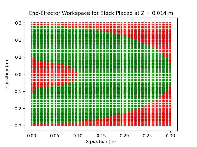 Middle of First Block | 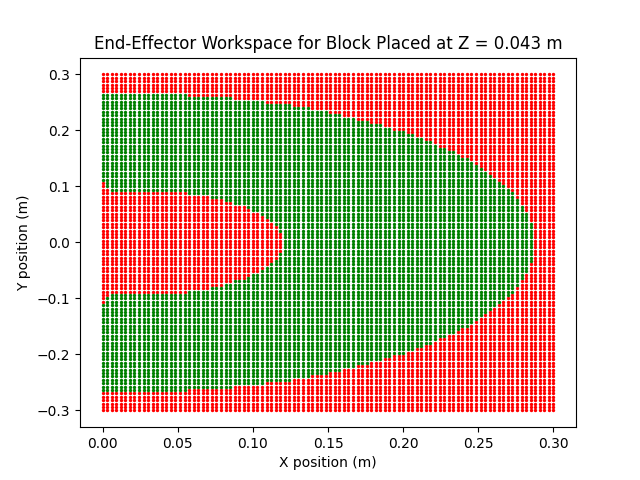 Middle of Second Block |
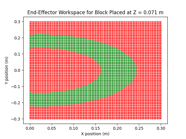 Middle of Third Block | 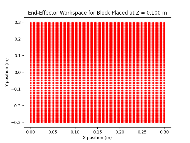 Middle of Fourth Block |
Your final video submission should look something like this:
Assignment Part 3 (Optional): Pick and Place to Stack Three Blocks
If you want an extra challenge, try stacking three blocks instead of two! You will need to make sure that your block and target positions are all within the workspace of the manipulator arm at their respective heights.
Proof that it’s possible:
Suggested Improvements
There are a few things that we can do to improve the tracking performance during our pick-and-place maneuver.
Adding Starting Configuration to move_to_pose
One suggestion is to modify the move_to_pose helper function to take in a desired starting location rather than taking the readings from the encoders as the starting location. This will reduce the discontinuity that occurs from the steady-state error.
def move_to_pose(bus, starting_position, desired_position, duration):
    start_time = time.time()

    while True:
        t = time.time() - start_time
        if t > duration:
            break

        # Interpolation factor [0,1] (make sure it doesn't exceed 1)
        alpha = min(t / duration, 1)

        # Interpolate each joint
        position_dict = {}
        for joint in desired_position:
            p0 = starting_position[joint]
            pf = desired_position[joint]
            position_dict[joint] = (1 - alpha) * p0 + alpha * pf

        # Send command
        bus.sync_write("Goal_Position", position_dict, normalize=True)

        # (Optional) Read back
        present_pos = bus.sync_read("Present_Position")
        print(present_pos)

        time.sleep(0.02)  # 50 Hz loop
This change will need to be propogated through the rest of your code. Everywhere that you call
move_to_poseyou will need to also provide the desired starting configuration of your motion. Since this is a fairly large change, I recommend implementing it in simulation first.
Submission Details
Please show your simulation to one of the TAs during lab office hours. The TAs will test your implementation by giving you random initial block locations and a random final target location (all within the workspace). If this is not possible, please include in your video submission yourself entering various target block locations to show that the inverse kinematics is working accurately. For full credit, each group member must also submit a writeup of the lab this week, how they implemented the code, and any issues encountered. The writeup should be a minimum of one paragraph.