The SO-101 Robot Arms
For this module, we will be writing code to calculate the forward kinematics for our SO-101 robot arms and execute a simple “Pick and Place” maneuver from pre-determined joint angles. This approach is often used for manufacturing robots where the starting and ending configurations are known apriori. But once we learn inverse kinematics, we will repeat this module using only the desired starting and ending cartesian positions of our end-effector.
Outline
- Assignment Part 1: Forward Kinematics
- Assignment Part 2: Write Pick and Place code
- Submission Details
Assignment Part 1: Forward Kinematics
1a) Write Forward Kinematics Helper Function
This is the first time we will be implementing forward-kinematics for our SO-101 robot arms! To do this, write a helper script named so101_forward_kinematics.py that takes computes the tool frame position and orientation given a dictionary item of the robot configuration. To help you write this, I’ve provided a start to this script below that shows how to compute the first transformation in our product of Lie groups method:
import time
import mujoco
import numpy as np

def Rx(thetadeg):
    thetarad = np.deg2rad(thetadeg)
    c = np.cos(thetarad)
    s = np.sin(thetarad)
    return np.array([[1, 0, 0],
                     [0, c, -s],
                     [0, s, c]])

def Ry(thetadeg):
    thetarad = np.deg2rad(thetadeg)
    c = np.cos(thetarad)
    s = np.sin(thetarad)
    return np.array([[c, 0, s],
                     [0, 1, 0],
                     [-s, 0, c]])

def Rz(thetadeg):
    thetarad = np.deg2rad(thetadeg)
    c = np.cos(thetarad)
    s = np.sin(thetarad)
    return np.array([[c, -s, 0],
                     [s, c, 0],
                     [0, 0, 1]])

def get_gw1(theta1_deg):
    displacement = (0.0388353, 0.0, 0.0624)
    rotation = Rz(180) @ Rx(180) @ Rz(theta1_deg)
    pose = np.block([[rotation, np.array(displacement).reshape(3,1)], [0, 0, 0, 1]])
    return pose
Your forward kinematics should be based on the diagram shown below. The information shown on the diagram was obtained directly from the so-101 urdf used in Assignment 5.
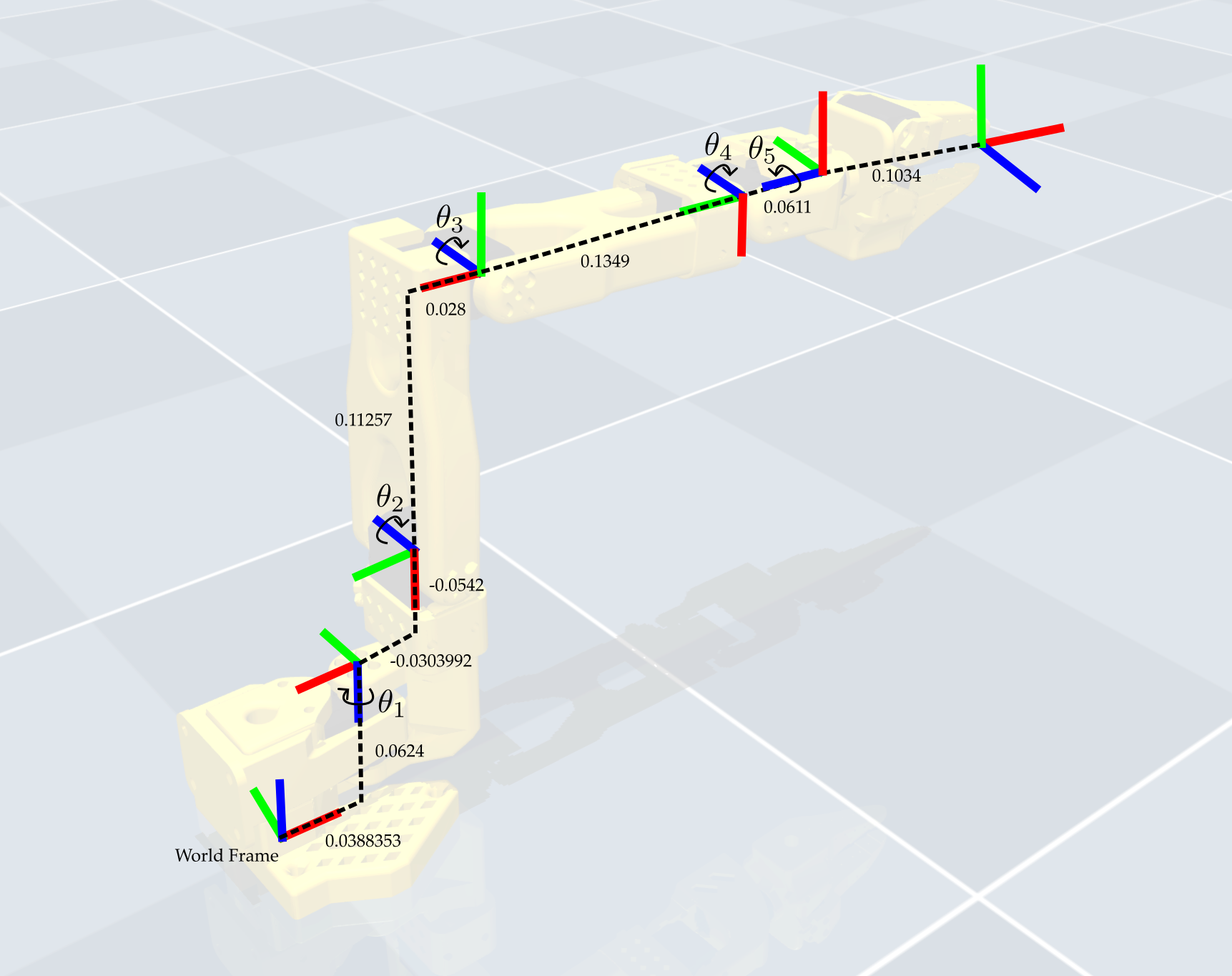
Since we are interested in the position of objects within the moving jaw’s grasp, we added an object frame as shown on the diagram. This object frame is directly translated/rotated from joint 5. This means that in our forward kinematics mapping we will actually ignore joint 6 (since the moving jaw does not influence where the object would be located). This is the same procedure/methodology as what we’ve been doing with the tool frame in class.
When you complete all of the get_gxx() functions, you can obtain the entire forward kinematics as follows:
def get_forward_kinematics(position_dict):
    gw1 = get_gw1(position_dict['shoulder_pan'])
    g12 = get_g12(position_dict['shoulder_lift'])
    g23 = get_g23(position_dict['elbow_flex'])
    g34 = get_g34(position_dict['wrist_flex'])
    g45 = get_g45(position_dict['wrist_roll'])
    g5t = get_g5t()
    gwt = gw1 @ g12 @ g23 @ g34 @ g45 @ g5t
    position = gwt[0:3, 3]
    rotation = gwt[0:3, 0:3]
    return position, rotation
1b) Test Forward Kinematics in MuJoCo
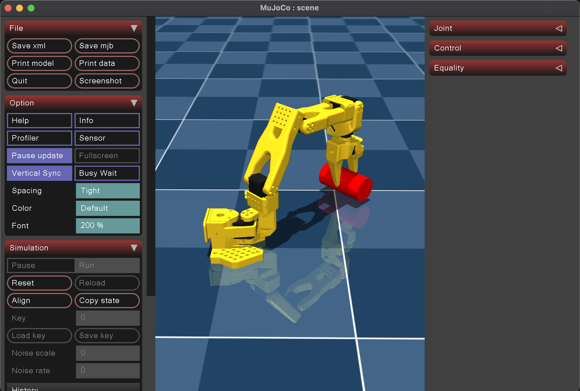
To test whether or not your forward kinematics are valid, we will use a method similar to that done for the homework component this week. This method will plot an additional cylinder along the z-axis of the tool frame. If you’ve done your forward kinematics correctly, you should see the cylinder in the gripper when you run the following test script:
import time
import mujoco
import mujoco.viewer
from so101_mujoco_utils import set_initial_pose, send_position_command, move_to_pose, hold_position
from so101_forward_kinematics import get_forward_kinematics
import numpy as np

m = mujoco.MjModel.from_xml_path('model/scene.xml')
d = mujoco.MjData(m)

def show_cylinder(viewer, position, rotation, radius=0.0245, halfheight=0.05, rgba=[1, 0, 0, 1]):
    # Add a cylinder aligned with z-axis
    mujoco.mjv_initGeom(
        viewer.user_scn.geoms[0],
        type=mujoco.mjtGeom.mjGEOM_CYLINDER,   # cylinder type
        size=[radius, halfheight, 0],                  # [radius, half-height, ignored]
        pos=position,                         # center position
        mat=rotation.flatten(),              # orientation matrix (identity = z-up)
        rgba=rgba                           # color
    )
    viewer.user_scn.ngeom = 1
    viewer.sync()
    return

test_configuration = {
    'shoulder_pan': -45.0,   # in radians for mujoco!
    'shoulder_lift': 45.0,
    'elbow_flex': -45.00,
    'wrist_flex': 90.0,
    'wrist_roll': 0.0,
    'gripper': 10
}

set_initial_pose(d, test_configuration)
send_position_command(d, test_configuration)

object_position, object_orientation = get_forward_kinematics(test_configuration)

with mujoco.viewer.launch_passive(m, d) as viewer:
  # Close the viewer automatically after 30 wall-seconds.
  start = time.time()

  # Add a cylinder as a site for visualization
  show_cylinder(viewer, object_position, object_orientation)

  # Hold Starting Position for 2 seconds
  hold_position(m, d, viewer, 20.0)
Assignment Part 2: Write Pick and Place code
2a) Test Pick and Place in MuJoCo
We will first conduct the pick and place maneuver in simulation. This will require modifying the code above to have six different joint configurations, and transitioning between these joint configurations using our hold_position and move_to_pose functions from the last two assignments. The first and last configurations should be the following:
starting_configuration = {
    'shoulder_pan': -45.0,   # in radians for mujoco!
    'shoulder_lift': 45.0,
    'elbow_flex': -45.00,
    'wrist_flex': 90.0,
    'wrist_roll': 0.0,
    'gripper': 50
}
final_configuration = {
    'shoulder_pan': 45.0,   # in radians for mujoco!
    'shoulder_lift': 45.0,
    'elbow_flex': -45.00,
    'wrist_flex': 90.0,
    'wrist_roll': 0.0,
    'gripper': 50
}
The second and second-to-last configurations should then be these same configurations but with the gripper closed:
starting_configuration_closed = {
    'shoulder_pan': -45.0,   # in radians for mujoco!
    'shoulder_lift': 45.0,
    'elbow_flex': -45.00,
    'wrist_flex': 90.0,
    'wrist_roll': 0.0,
    'gripper': 5
}
final_configuration_closed = {
    'shoulder_pan': 45.0,   # in radians for mujoco!
    'shoulder_lift': 45.0,
    'elbow_flex': -45.00,
    'wrist_flex': 90.0,
    'wrist_roll': 0.0,
    'gripper': 5
}
The middle two configurations should be determined by you in order to move the manipulator arm upwards so that it doesn’t interfere with the table or any other obstacles that might be on the table.
Your final code should produce the video shown below:
The following code was used to visualize the cubes in the simulation video:
def show_cubes(viewer, starting_config, final_config, halfwidth=0.013):
    # Use forward kinematics
    starting_object_position, starting_object_orientation = get_forward_kinematics(starting_config)
    final_object_position, final_object_orientation = get_forward_kinematics(final_config)

    # Add starting cube
    mujoco.mjv_initGeom(
        viewer.user_scn.geoms[0],
        type=mujoco.mjtGeom.mjGEOM_BOX,
        size=[halfwidth, halfwidth, halfwidth],
        pos=starting_object_position,
        mat=starting_object_orientation.flatten(),
        rgba=[1, 0, 0, 0.2]
    )
    # Add final cube
    mujoco.mjv_initGeom(
        viewer.user_scn.geoms[1],
        type=mujoco.mjtGeom.mjGEOM_BOX,
        size=[halfwidth, halfwidth, halfwidth],
        pos=final_object_position,
        mat=final_object_orientation.flatten(),
        rgba=[0, 1, 0, 0.2]
    )
    viewer.user_scn.ngeom = 2
    viewer.sync()
    return
2b) Execute Pick and Place on Hardware
Once you’re comfortable with this process of moving from joint configuration to joint coniguration, try it out on the real robot! You should mostly be able to use your code from Assignment 3 with the addition of a few more target joint configurations and move_to_pose calls. The general procedure is the following.
- Determine the object locations using our predictions from the forward kinematics mapping and place the objects in this position using our acrylic cartesian grids.
- Start your code as in Lab 3 where we store the robot’s actual starting position and move to the first desired joint configuration using:
starting_pose = bus.sync_read("Present_Position")
move_to_pose(bus, starting_configuration, 2.0)
At the end of your code, you should then transition back to the initial starting position using
move_to_pose(bus, starting_pose, 2.0)
This will prevent the robot from slamming into the table when it terminates the script.
- Execute the full sequence and verify that it visually matches what we see in simulation. In particular, does the first desired configuration align with our expected object location? In your writeup, comment on whether or not this prediction was accurate.
- If the initial object location is not accurate, you may need to recalibrate. If it is still not accurate, you can use the
read_positionscript from Assignment 3 to find a more appropriate starting and final joint configuration. Note that this will require also modifying the in-between joint configurations. - Show the TAs your robotic simulation and hardware. More details on the requirements for the assignment submission this week are provided below.
Your final robotic demonstration should look like the following:
Please put away all supplies and return the desk to a clean position when you are done with lab. Please also let us know if anything breaks so that we can maintain the robots.
Submission Details
For the homework assignment, please show your robot behavior and simulation to one of the TAs during the lab office hours. If this is not possible, you may also email a video to the TAs (with Prof. Tucker cc-ed), but we would much prefer in-person demonstrations. For full credit, each member of each group must also write their own writeup (included in the homework submission) about what was implemented, and any challenges/difficulties that you had when writing/executing the code.